Hypercube with Tokymaker
Author: Highping
This text is extracted from Highping project and modified to be used with Tokymaker instead of ESP8266.
"Short video and some more pics: https://www.youtube.com/watch?v=CBXwCJqZ-Yg.
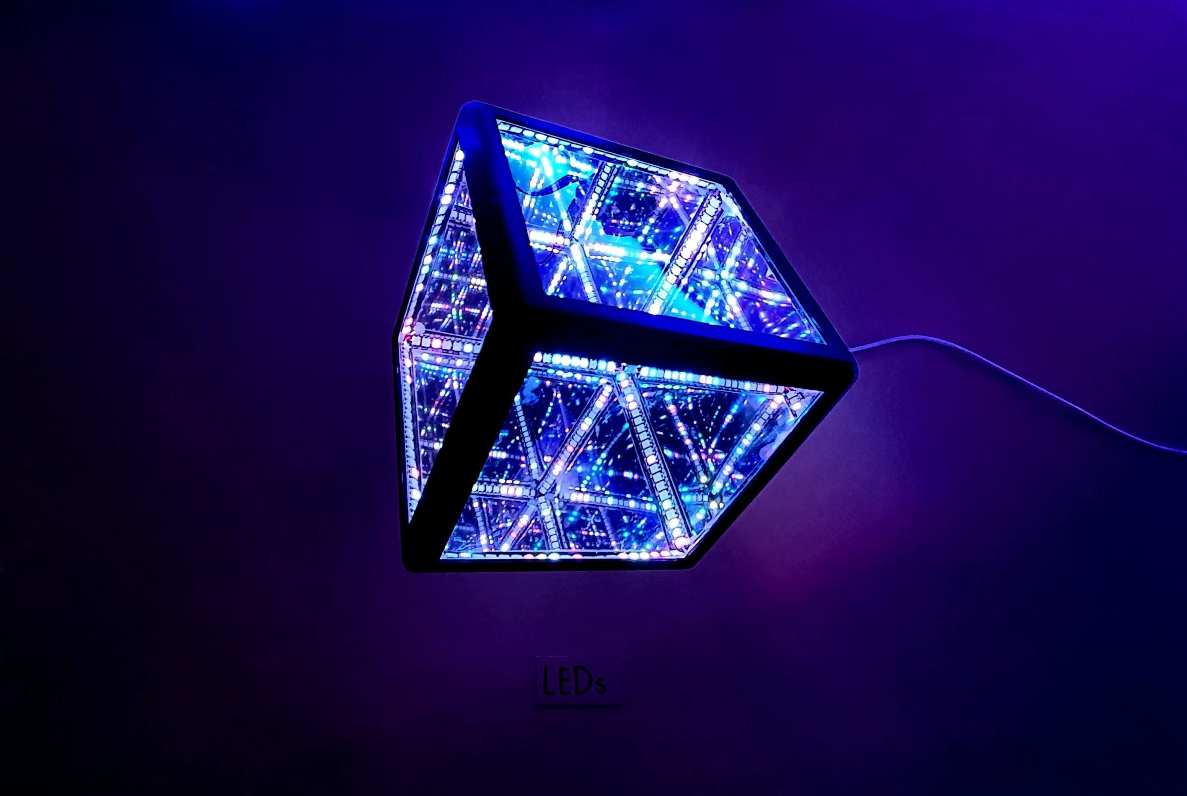
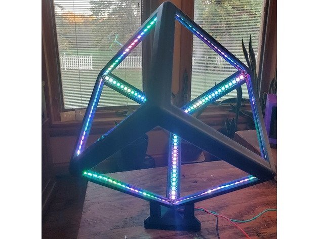
I have seen many variations of the Infinity Cube around lately, so I decided to build one of my own. This was a fun but challenging build for me, and I am pretty happy with the results, so I thought I would share in case others want to have a go. Below I have tried to cover most of the steps and some of the things I ran into while building this. If anyone has questions, I will try to answer them.
Material:
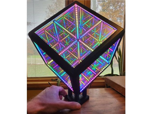
- 3D printed frame (3 piece model)
- 1 Meter strips of WS2812B. (I used the 144/M style)
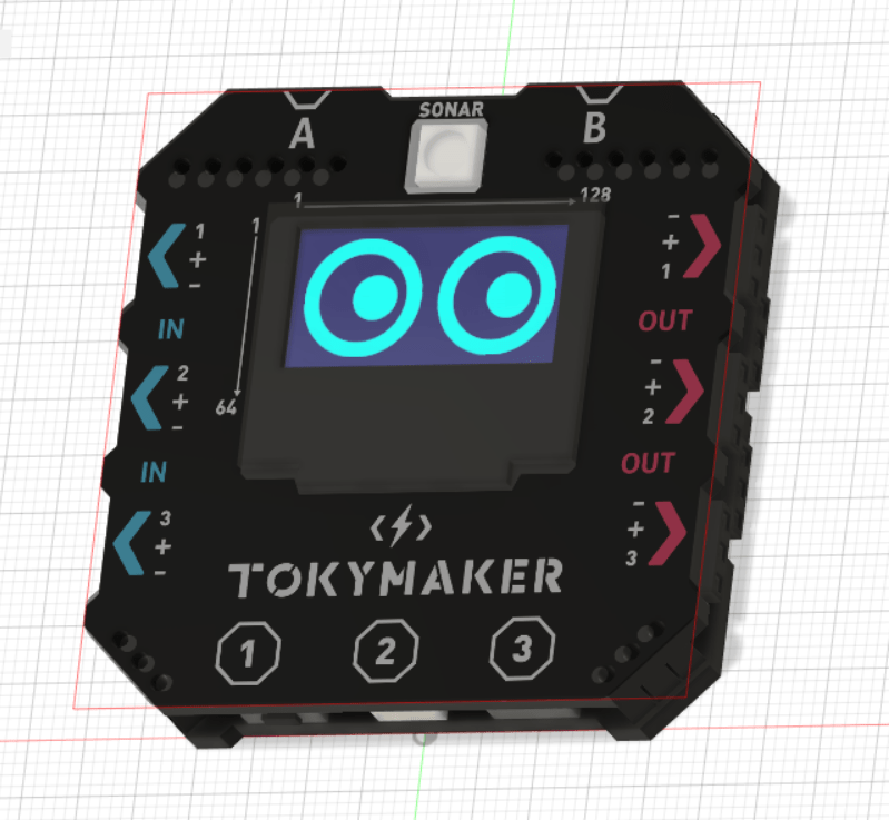
- Tokymaker
- standard micro-switch (optional)
- 143mm (5-5/8 in) x 3mm one-way mirror
Preparation:
Print the frame and attach the top to the bottom with some 2mm screws (or you can just glue it if you don't have the screws).
It might be a good idea to print the bottom piece first and make sure your lights fit into the channel before doing the (long) top print. My lights were originally about a mm too wide, so I had to trim them a little, but the uploaded model here should be right for any standard strip (about 11mm).
Once you have the bottom of the cube printed you can get a definite length of the strips you will need. (Mine ended up being 21 LEDs per segment). Cut your LEDs into 12 pieces of the same length. Try to get as centered on the pads as you can when you cut them.
It would be a good idea to go ahead and "tin" the contacts on both ends of every segment while they are laid out flat on the bench. It will make life much easier later in the build.
Lights Install:
This is the toughest part of the whole build.
Layout:
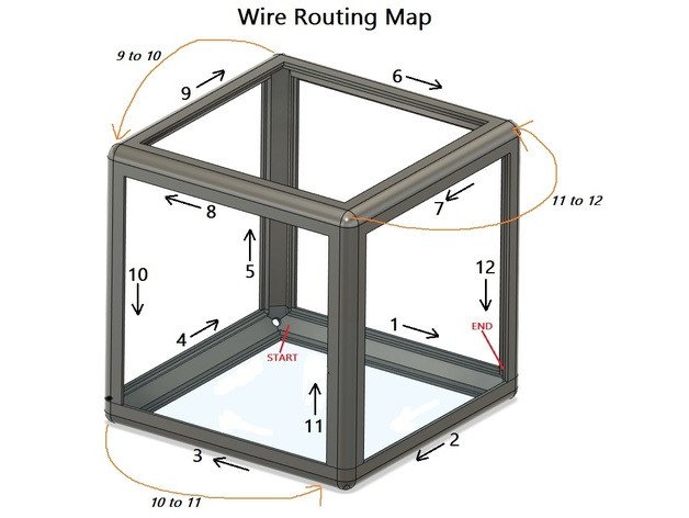
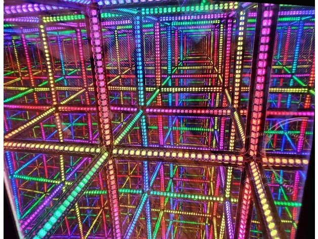
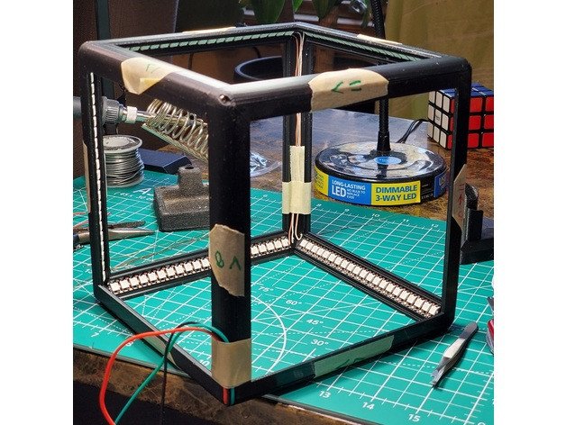
Because these lights need to run in a continuous, one-way circuit, it is important to maintain the layout throughout the soldering process. This becomes quite difficult to keep track of on an object that is symmetrical in every axis. I recommend using some painter's tape to label each rail of the cube with its number and also be sure to mark the direction (see diagram and photo). The direction is key. Your lights will be marked with an arrow. Make sure the arrow on the lights always follows the path you have laid out with your tape.
One important thing about the layout is that there is no way to run a continuous line around every leg of a cube. The line has to double back at least 3 times. In the diagram, you will see that I have done these 'loopbacks' on the final 3 legs (10,11,12). In these connections (marked in orange in the diagram), you will need to run the wires under one LED strip. Because of this, I recommend starting at the end and working back... Insert lights on leg-12 and on leg-11, and then run and solder the wires between them. then 11 to 10, 10 to 9, and so on.
Wiring and Soldering
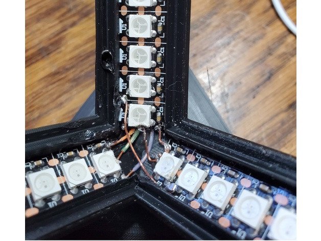
The wire I used for this was just stripped from a piece of ethernet cable (CAT5, 4 twisted pair). These wires were small enough to fit nicely under the strips in the loopback connections, and the solid core also made it easy to bend them into some sort of shape to bridge the various connections. Just take a piece that is long enough to hold, and put a bend in the end of it to match the connection you are bridging. Then (because you tinned the pads before hand) you should be able to hold it steady and touch your iron to it. Then after the solder cools, just clip the long piece away.
I highly recommend that you test the strip after soldering each segment. You really want to do the troubleshooting as you go with this, because tracking down and repairing issues after all the lights are in would be difficult. I rigged up some wires to the little inline controller that came with my light strips, and used those to touch the contacts of each strip as I went. This lets you find and fix bad solder joints (or fried leds) as you go. By checking your work with each segment, you will get better at figuring out what you did wrong and fixing it. These little contacts (especially after being cut in half) are very touchy to solder to, but by the time you get through the 72 total solder joints inside this cube, you will be a bit of an expert at it (note: do not refer to my pics for what "a bit of an expert" looks like)
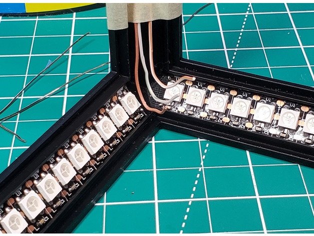
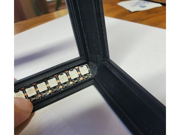
Another Tip: At some point I figured out that it is much easier to make the power connections using the 'inner pads' (the full, uncut pads) instead of using the half pads at the end of the strip (see photos). You only have to use the end pads for the data line. The power can tie in anywhere on the strip.
After you have worked your way all the way around to segment 1, make the final wires (the ones at the very beginning of the arrow stream) long enough to run through the hole in the corner. If you somehow missed that hole when you started, rip it all out and start again.... kidding.... if for some reason you didn't end at the hole just drill a new one. (hint: you might also be surprised at how easily you can poke a hole through PLA with a cheap soldering iron ;).
If you made it this far and all your lights work, you are over the hardest part of this build. The rest is cake.
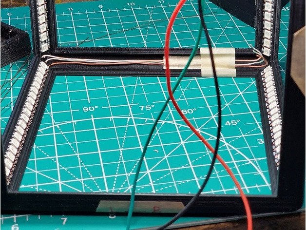
Install and Setup Controller:
After the soldering of all the lights, the connections to the controller are pretty simple. Just follow the wiring diagram and refer to the photo. Leave the wires long enough to make the connections, but short enough to be able to be tucked under the controller when you glue it in (note: rather than gluing it, I noticed I could just melt over some little 'tabs' with the soldering iron to hold it in (total accident, but it seemed to work so I rolled with it).
After you have the controller installed, there are many different options for controlling the leds. What I am using (and what I recommend using) is WLED. It's easy to install, pretty versatile, and can be app or web controlled. There's lots of info on using WLED out there, but you should be able to get it installed with the instructions here: https://kno.wled.ge/basics/getting-started/
(note: you can also use WLED to configure different functions into the micro switch button so it can run stand alone without any wifi)
Installing Mirror Panels:
Warning: This is the last step of the build. Once you glue in the last panel there is no easy way back in there if a loose connection shows up. I highly recommend doing a double/triple check of all your connections before sealing this thing up. The way I did this was by taking a wooden toothpick (non-conductive) and gently raking it across all my connections (while the lights were on a solid pattern). If you see any flicker as you bump across the wires, go back in with your soldering iron and make it solid. I found at least 4 connections that needed work on mine.
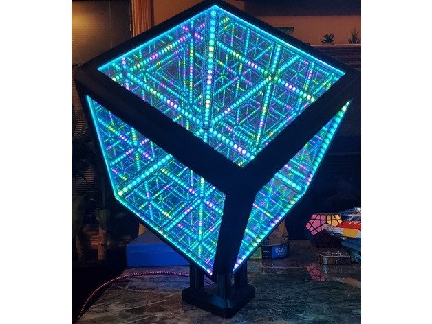
I used 3mm thick pre-mirrored acrylic here, but it could also be done with standard acrylic and mirror film. I tried this, but wasn't thrilled with my results, so I ordered the pre-mirrored stuff. The place I got mine even pre-cut it to the right dimensions. Having done both, it was much less work and much better outcome using the pre-made and only slightly higher cost.
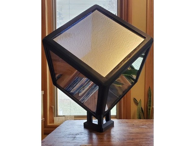
Once you have test fit all your pieces, it's just a matter of gluing them in. I used a tiny dab of hot glue in the very corners of the first 5 panels (from the inside). The last panel is the tricky one. You need either use a little suction cup, or you can prop the cube in a way that you can insert it from the bottom and let gravity hold it down. I used a little drop of CA glue in the corners of the final piece and then held it there with the suction cup until it dried.
That should be it! At this point you should be able to pull out your phone, and start playing with the WLED app to find all the settings and patterns you like.
Print SettingsNotes:
Supports only needed on the "Base/Stand" piece
Programming
This part couldn't be easier, just connect the lights to the OUT 1 of the Tokymaker, upload the code included in this downloadable and enjoy!
NOTE:
Thank you Highping for this amazing project and allowing tokymaker to shine in such project!