EEZYbotARM Mk2 - 3D Printed Robot
Author: theGHIZmo
This is an extract of the article posted in Instructables, with modified information to adapt the functioning to tokymaker platform. Enjoy!
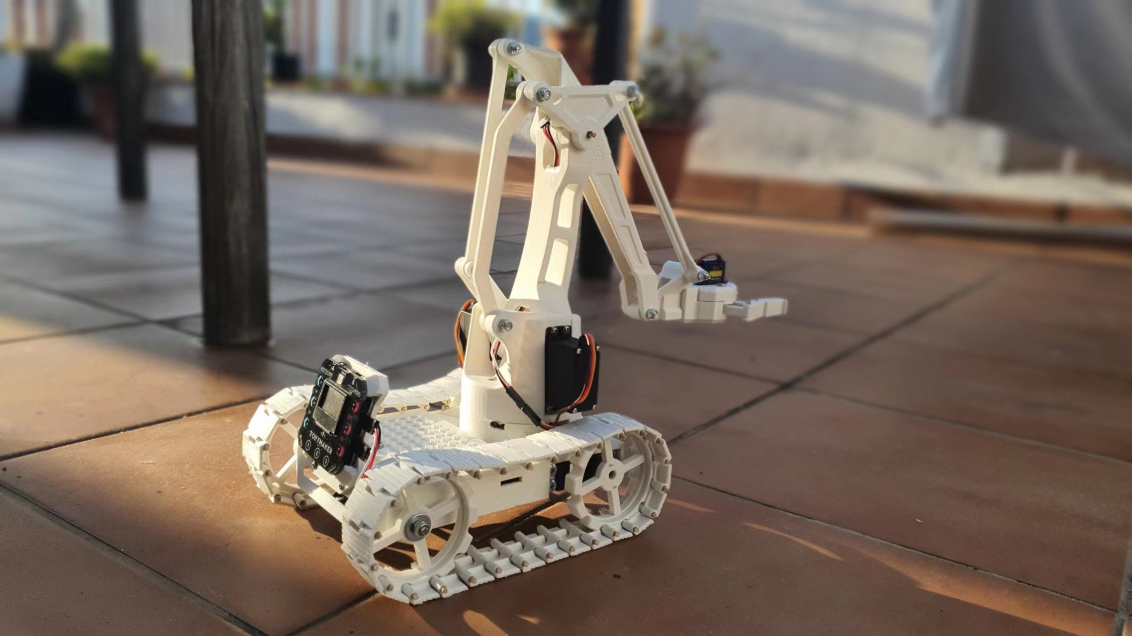
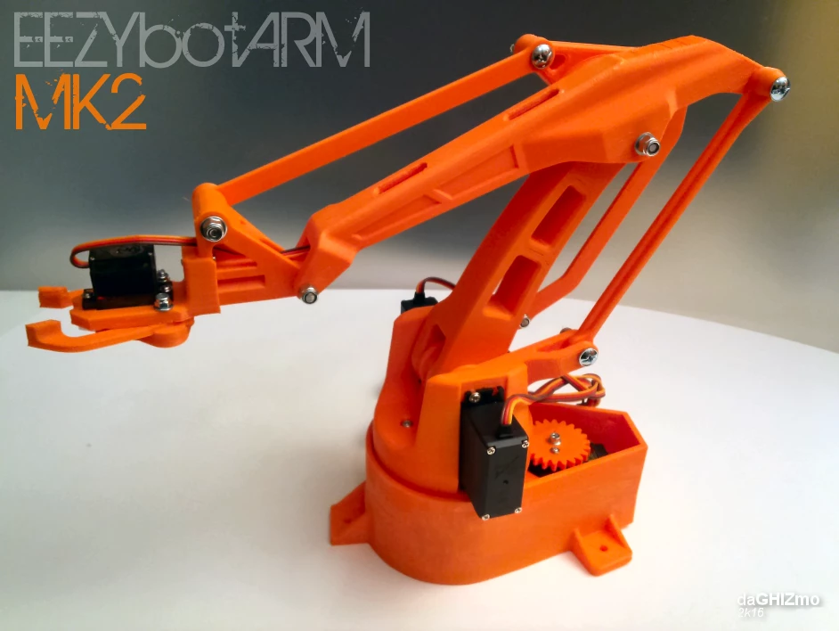
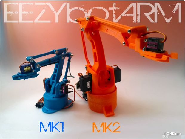
This is a four axis 3D printed robotic Arm.
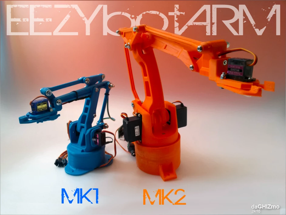
It follows the success of my previous smaller one: the EEZYbotARM so I simply called it MK2 (make 2). It is a little bigger and stronger, just to obtain more payload and increase reach.
I implemented also some little features like: a replaceable gripper with quick coupler, internal cable routing in main big arms and the vertical axis supported by spheres.
It has been designed without a definite purpose, the aim is educational, providing a suitable hardware that allow to concentrate on exploring all its potential applications.
Following the requests of many users I made available the whole project on my Onshape account. You can find the source CADfiles at this link EEZYbotARM mk2. You can copy and modify the files, designing your own version. Please follow the original licence and provide attributions.
EEZYbotARM Mk2 has been initially released on my Thingiverse account here: thing 1454048
You can find a dedicated instructable of the smaller mk1 at this link :EEZYbotARM instructable
You can find more DIY projects at my personal web page www.eezyrobots.it
Step 1: NOTES
3D PRINTING :
It is a little more challenging to print than the mk1 due to it's dimensions and also some parts geometry.
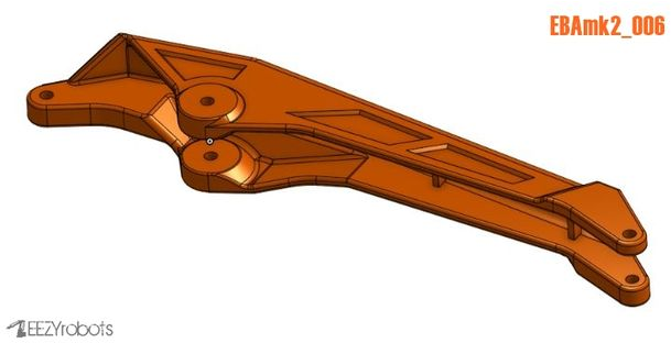
Some few components (like main horizontal arm 006) requires supports enabled and a printing area of 200x200 millimeters. I supply all stl models already correctly oriented to avoid supports when possible.
I printed all the parts using a Prusai3 with ABS filament, but also PLA works great.
I made available a short video of some of the parts printing on YouTube
It has been replicated may times and you can view at Thingiverse users make
HARDWARE :
I used metric hardware and all joints rotate on M4 screws. (in alternative of M4 an #8-32 can be used) Holes of the joints are designed quite tight. This to allow a fine adjust of their diameter using an exact drill bit.
On screws are to be used selflocking nuts. They are to be tightened till the locking of the joint, then consequently you have to loose them until you obtain a smooth movement with a low clearance between components. On the two axis of the main vertical.arm I used M4 threaded rods
Step 2: Parts and Materials
Here following the list of parts necessary to built the mk2 robotic arm.
You need some 3D prinded parts and some commercial items. If you do not have a 3D printer there are several 3D printing services like 3D Hubs that can do the work for you.
Commercial items can be easy found on the web. You mainly need 3 big servos MG995 or MG946 (they are dimensionally the same, but 946 are a little more powerful). Then a small sg90servo, a 606 bearing and some steel spheres with a diameter of 6 mm. The remaining are components that can be found ol local hardware stores (remenber only that I use metric hardware)
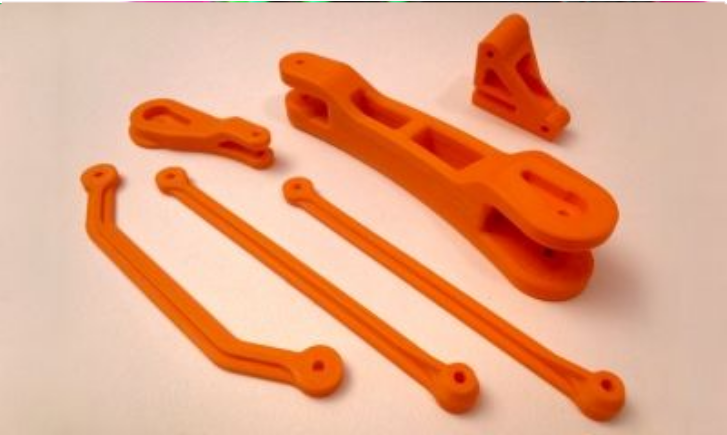
3D PRINTED PARTS BOM list :
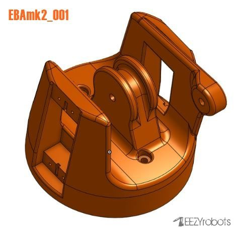
- EBAmk2_001_base.STL
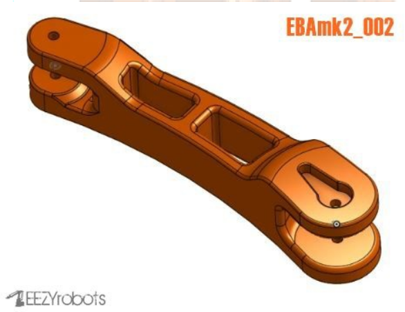
- EBAmk2_002_mainarm.STL
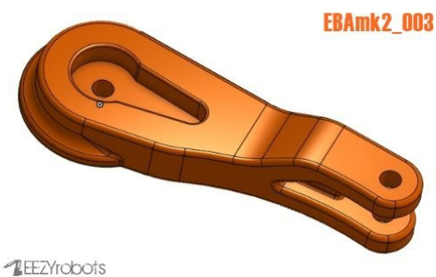
- EBAmk2_003_varm.STL
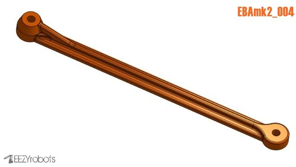
- EBAmk2_004_link135.STL
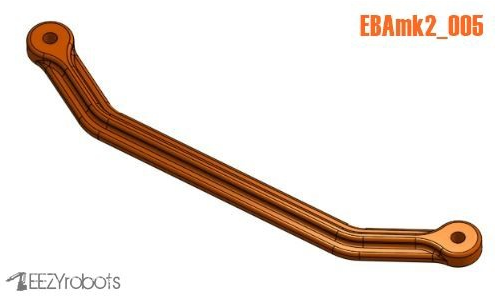
- EBAmk2_005_link135angled.STL
- EBAmk2_006_horarm .STL
- EBAmk2_006_horarm_plate.STL
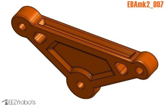
- EBAmk2_007_trialink.STL
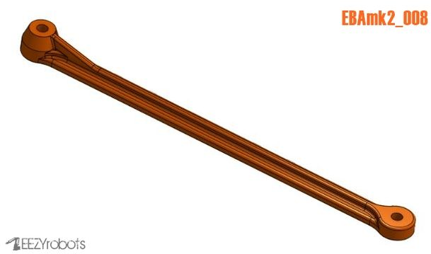
- EBAmk2_008_link147_new.STL
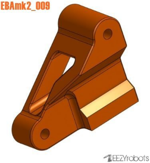
- EBAmk2_009_trialinkfront.STL
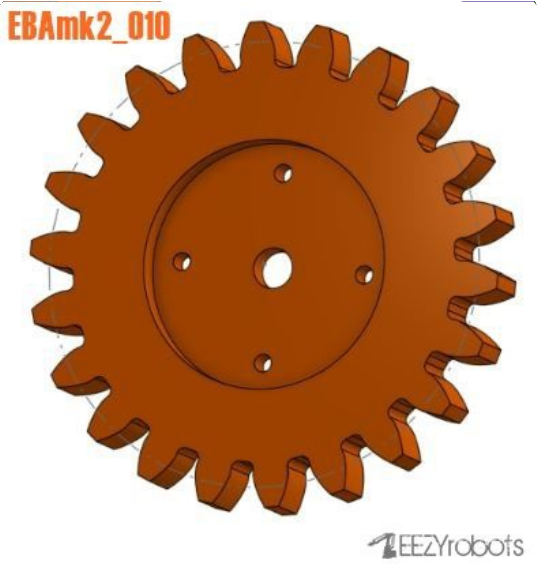
- EBAmk2_010_gearservo.STL
- EBAmk2_010_gearservo_22DENTI.STL
- EBAmk2_010_gearservo_25DENTI.STL
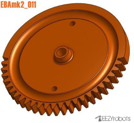
- EBAmk2_011_gearmast.STL
- EBAmk2_012_mainbase.STL
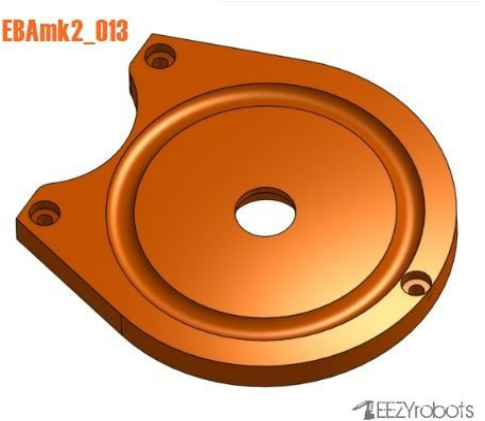
- EBAmk2_013_lower base.STL
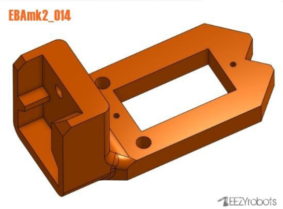
- EBAmk2_014_claw base.STL
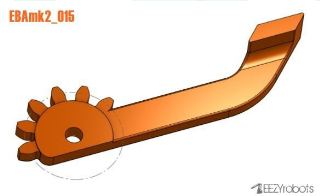
- EBAmk2_015_claw finger dx.STL
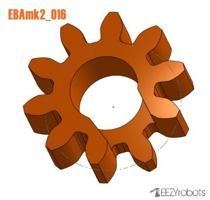
- EBAmk2_016_claw gear drive.STL
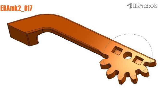
- EBAmk2_017_claw finger sx.STL
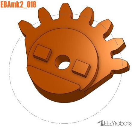
- EBAmk2_018_claw gear driven.STL
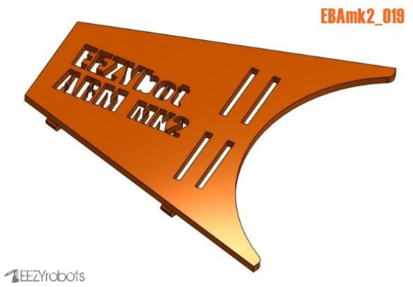
- EBAmk2_019_drive cover.STL
NON PRINTED PARTS BOM list :
- 3 - 955 or 946 servo
- 1 - SG90 SERVO
- 1 - M6 selflocking nut
- 1 - M6x25 screw
- 2 - M3 selflocking nuts
- 2 - M3 x 20 screws
- 1 - M3 x 10 hex recessed head screw
- 9 - M4 selflocking nuts
- 1 - M4 x 40 screw
- 1 - M4 x 30 screw
- 5 - M4 x 20 screw
- 1 - M4 x 60mm threaded rod
- 1 - M4 x 32mm threaded rod
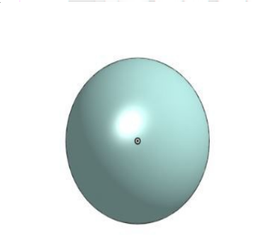
- 25 - dia 6 mm ball spheres
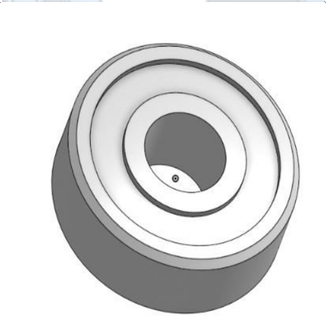
- 1 - 606zz bearing
- some M4 washers
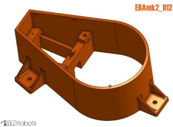
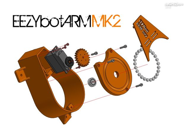
Step 3: Assembling the Main Base
Let's start assembling the main basefollowing the steps :
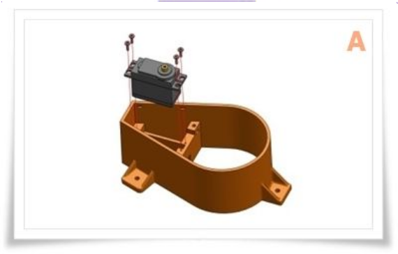
A - Put in position an MG946 servo with the driving shaft aligned forward. Fix the servo to the main base using the selftapping screws supplied with it.
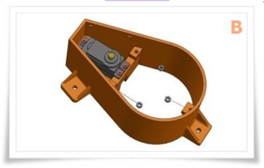
B - Insert 3 M3 nuts in the receptacles of the main base as swown.
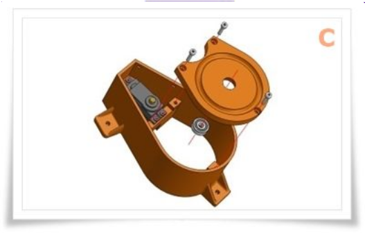
C - Insert the 606 bearings in its housing and attach the plate to the main base using 3 M3 screws. Verify the freedom of movement of the bearing.
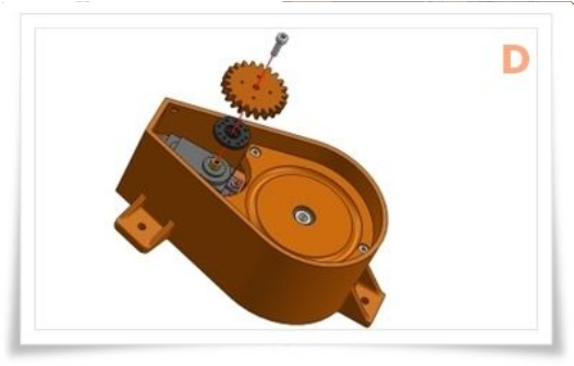
D - Position the drive plate on the splined shaft and upper the driving printed gear. Add one or two small selftapping screw to connect plate and the gear. ( There are two driving gears available one has 22 teeth and the other 25. I
made two because during printing of the base I've got some deformation and the two axis distance became smaller )
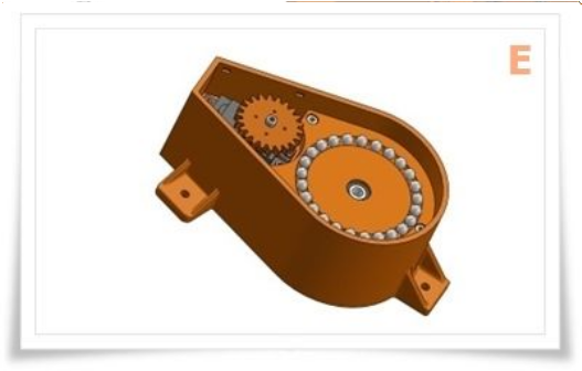
E - Fill the path using about 25 spheres with a diameter of 6mm.
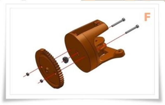
F - Insert an M6 self locking nut in the receptacle of the swivel base then place in position le geared base and fix it using a couple of M3 screws and nuts as shown.
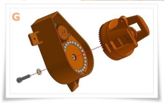
G - Keeping the main base flat and the swivel element in contact with it, connect the two elements using an M6 screw.
Step 4: Assembling the Main Arms
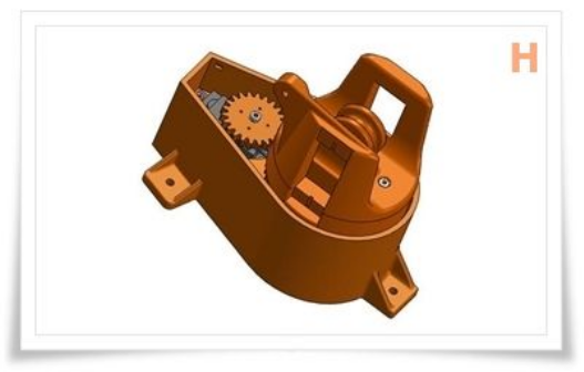
H - Now the main base is finished.
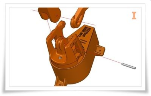
I - Put in position the main arm and the vertical drive lever, connect them
with the main base horizontal axis using a 4mm dia rod 33 mm long.
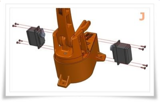
J - Fix in position the two servo and hold in place using eight selftapping screws. To drive the arms use the sigle horns supplied with the servos. Make sure that the mid position of the servos are aligned with the housing of the arms
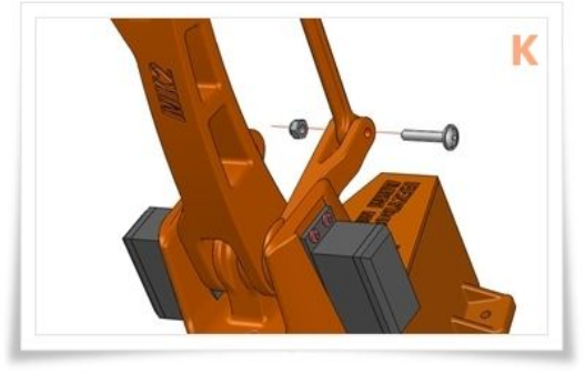
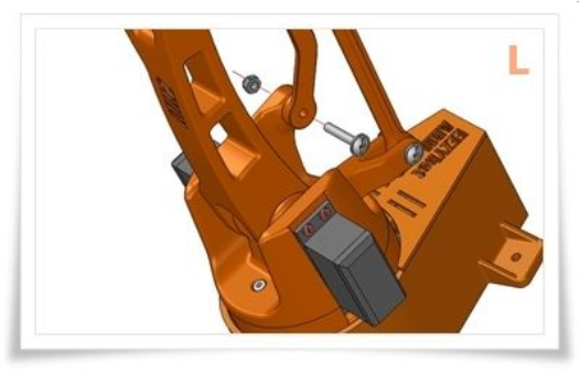
K - Connect the lower end of straight lever to the driving arm.
L - Connect the lower end of angled lever to the fixed end on the base.
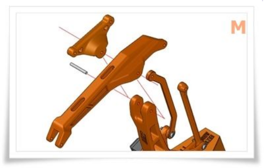
M - Use a threated M4 rod to connect the horizontal arm and the triangle to the upper part of the main arm.
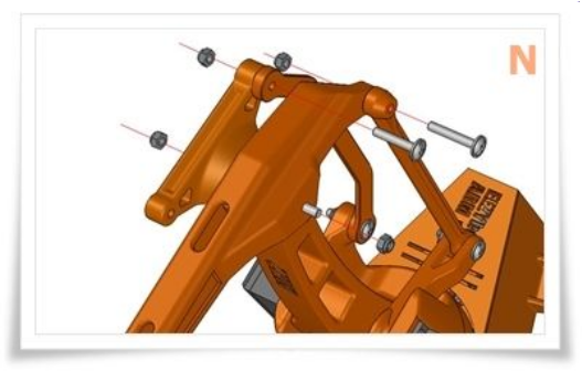
N - Connect the straight rod to the main arm and angled to the triangle.
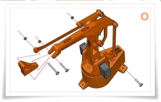
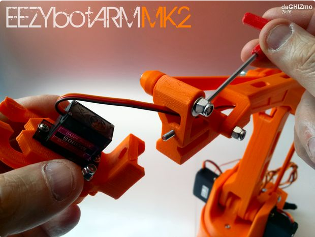
Step 5: Assembling the Gripper
O - Attach the rod and the fast release of the gripper, to the front part of the horizontal arm.
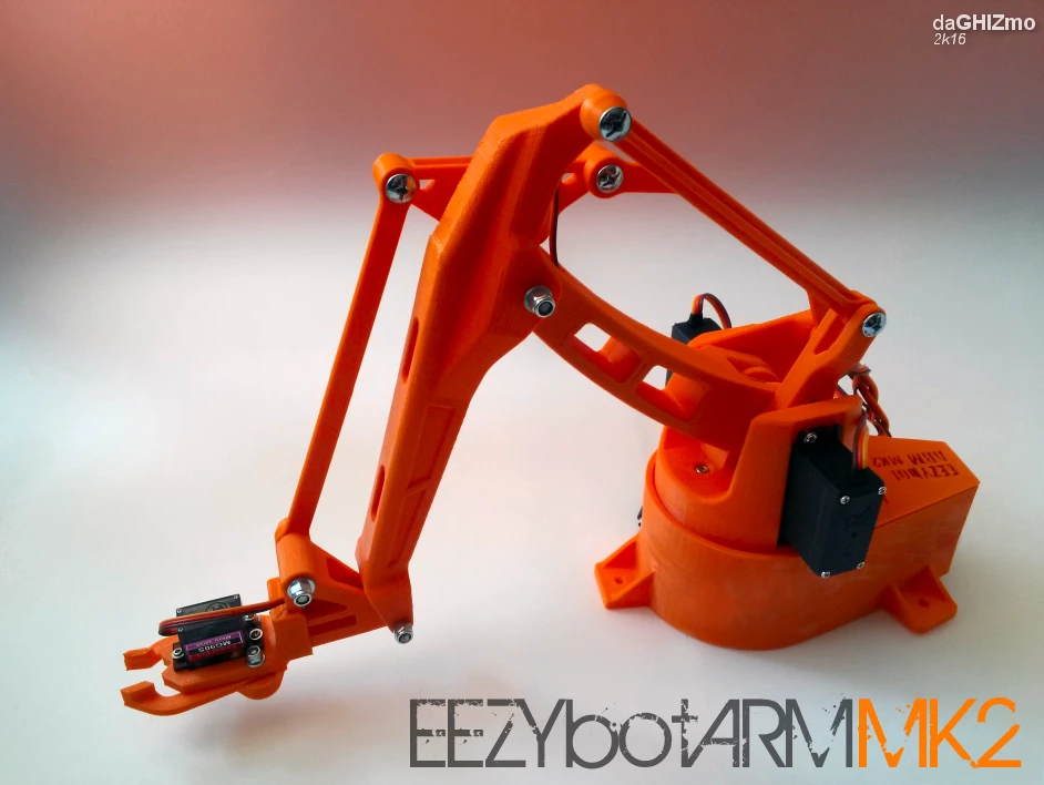
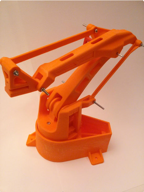
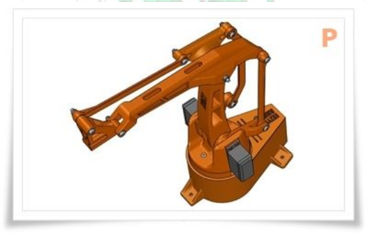
P - The robotic arm is now assembled.
You can now proceed with the gripper assembly or you can use your own gripper design
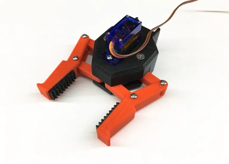
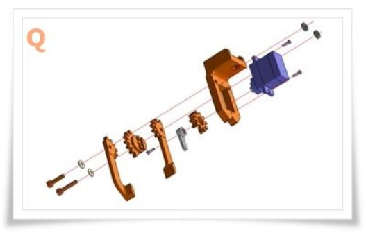
Q - Assembly the gripper as shown in the image "Q".
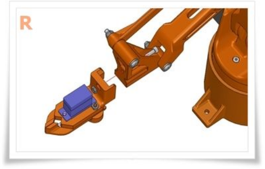
R - Attach the gripper to the fast release at the end of the arm and make the servo wire pass in the internal space of the horizontal arm.
Collect all the wires on the rear side of the robot leaving enough freedom of movements expecially on the rotation of vertical axis.
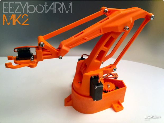
The eezybotarm mk2 is now mechanically assembled, ready to be driven by the electronics.

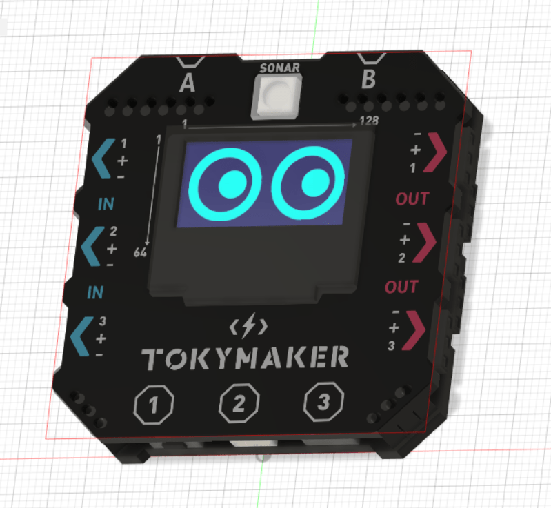
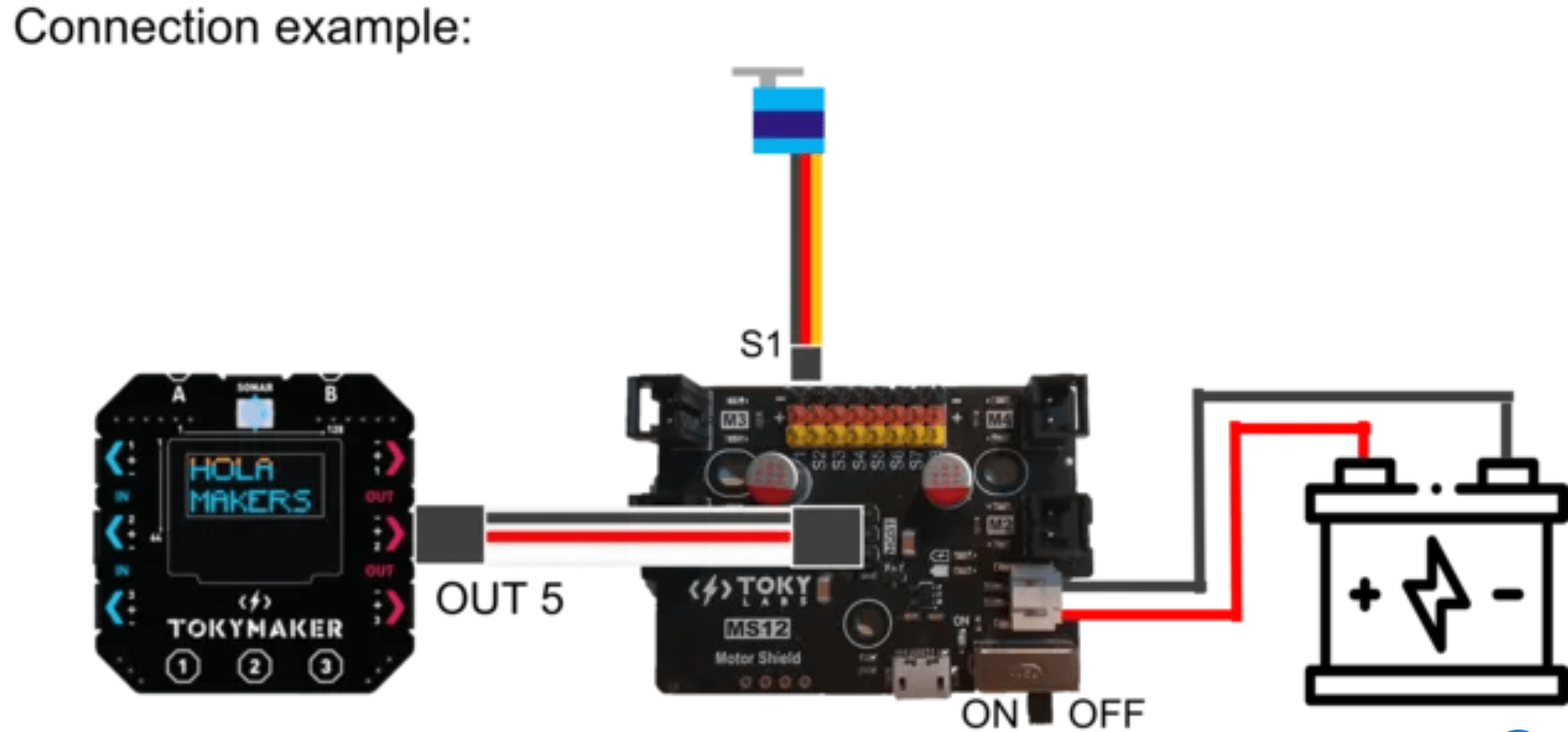
Step 6: Electronics
This step is very straightforward. Just connect all the servos to the motorshield. If you don't have a motorshield, go to this link: Tokylabs | Motor Shield
Step 7: Programming
Now, go to https://create.tokylabs.com and link the servomotors to the Gamepad included in Tokymaker. If you don't have a tokymaker, go here: Tokylabs | Tokymaker
If you want to know how we liked it, just download the code attached in the product.